MATLAB Simulink PROJECTS FOR Btech / Mtech STUDENTS

Key Features
- Graphical editor for building and managing hierarchical block diagrams
- Libraries of predefined blocks for modeling continuous-time and discrete-time systems
- Simulation engine with fixed-step and variable-step ODE solvers
- Scopes and data displays for viewing simulation results
- Project and data management tools for managing model files and data
- Model analysis tools for refining model architecture and increasing simulation speed
- MATLAB Function block for importing MATLAB algorithms into models
- Legacy Code Tool for importing C and C++ code into models
Building the Model
Simulink® provides a set of predefined blocks that you can combine to create a detailed block diagram of your system. Tools for hierarchical modeling, data management, and subsystem customization enable you to represent even the most complex system concisely and accurately.
Selecting Blocks
The Simulink Library Browser includes:
- Continuous and discrete dynamics blocks, such as Integration and Unit Delay
- Algorithmic blocks, such as Sum, Product, and Lookup Table
- Structural blocks, such as Mux, Switch, and Bus Selector
You can build customized functions by using these blocks or by incorporating hand-written MATLAB®, C, Fortran, or Ada code into your model.
Your custom blocks can be stored in their own libraries within the Simulink Library Browser.
Simulink add-on products let you incorporate specialized components for aerospace, communications, PID control, control logic, signal processing, video and image processing, and other applications. Add-on products are also available for modeling physical systems with mechanical, electrical, and hydraulic components.
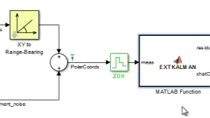
Building and Editing the Model
You build a model by dragging blocks from the Simulink Library Browser into the Simulink Editor. You then connect these blocks with signal lines to establish mathematical relationships between system components. Graphical formatting tools, such as smart guides and smart signal routing, help you control the appearance of your model as you build it. You can add hierarchy by encapsulating a group of blocks and signals as a subsystem in a single block.
The Simulink Editor gives you complete control over what you see and use within the model. For example, you can add commands and submenus to the editor and context menus. You can also add a custom interface to a subsystem or model by using a mask that hides the subsystem's contents and provides the subsystem with its own icon and parameter dialog box.
Navigating Through the Model Hierarchy
The Explorer bar and Model Browser in Simulink help you navigate your model. The Explorer bar indicates the level of hierarchy that you are currently viewing and lets you move up and down the hierarchy. The Model Browser provides a complete hierarchical tree view of your model, and like the Explorer bar, can be used to move through the levels of hierarchy.
Managing Signals and Parameters
Simulink models contain both signals and parameters. Signals are time-varying data represented by the lines connecting blocks. Parameters are coefficients that define system dynamics and behavior.
Simulink helps you determine the following signal and parameter attributes:
Data type—single, double, signed, or unsigned 8-, 16- or 32-bit integers; Boolean; enumeration; or fixed point Dimensions—scalar, vector, matrix, N-D, or variable-sized arrays Complexity—real or complex values Minimum and maximum range, initial value, and engineering units If you choose not to specify data attributes, Simulink determines them automatically via propagation algorithms, and conducts consistency checking to ensure data integrity. These signal and parameter attributes can be specified either within the model or in a separate data dictionary. You can then use the Model Explorer to organize, view, modify, and add data without navigating through the entire
Simulating the Model
You can simulate the dynamic behavior of your system and view the results as the simulation runs. To ensure simulation speed and accuracy, Simulink provides fixed-step and variable-step ODE solvers, a graphical debugger, and a model profiler.
Choosing a Solver
Solvers are numerical integration algorithms that compute the system dynamics over time using information contained in the model. Simulink provides solvers to support the simulation of a broad range of systems, including continuous-time (analog), discrete-time (digital), hybrid (mixed-signal), and multirate systems of any size. These solvers can simulate stiff systems and systems with discontinuities. You can specify simulation options, including the type and properties of the solver, simulation start and stop times, and whether to load or save simulation data. You can also set optimization and diagnostic information. Different combinations of options can be saved with the model.
Running the Simulation
You can run your simulation interactively from the Simulink Editor or systematically from the MATLAB command line. The following simulation modes are available: Normal (the default), which interpretively simulates your model Accelerator, which increases simulation performance by creating and executing compiled target code but still provides the flexibility to change model parameters during simulation Rapid Accelerator, which can simulate models faster than Accelerator mode by creating an executable that can run outside Simulink on a second processing core To reduce the time required to run multiple simulations, you can run those simulations in parallel on a multi-core computer or computer cluster.
Analyzing Simulation Results
After running a simulation, you can analyze the simulation results in MATLAB and Simulink. Simulink includes debugging tools to help you understand the simulation behavior.
Viewing Simulation Results
You can visualize the simulation behavior by viewing signals with the displays and scopes provided in Simulink. You can also view simulation data within the Simulation Data Inspector, where you can compare multiple signals from different simulation runs. Alternatively, you can build custom HMI displays using MATLAB, or log signals to the MATLAB workspace to view and analyze the data using MATLAB algorithms and visualization tools.
Debugging the Simulation
Simulink supports debugging with the Simulation Stepper, which lets you step back and forth through your simulation viewing data on scopes or inspecting how and when the system changes states.
With the Simulink debugger you can step through a simulation one method at a time and examine the results of executing that method. As the model simulates, you can display information on block states, block inputs and outputs, and block method execution within the Simulink Editor.
Managing Projects
Simulink provides tools to help you manage project-related files, components, and large amounts of data.
Managing Project-Related Files
Building Design Components
btech mtech matlab simulink Projects centers in kerala,matlab Projects centres in ernakulam,btech mtech matlab Projects center in cochin,matlab Projects in eranakulam,matlab project center Projects in thrissur,matlab Projects centre in kottayam,btech mtech matlab based project center,btech mtech matlab based project centre in ernakulam
PROJECTS
Our support Areas
Testimonials
![]() For a lustrum I know this institution and its mentors personally, the way of taking classes and the method they adopted in teaching and training students were really interesting and helpful to me and my friends. I was really impressed with the wide variety of classes offered by them. I had a very happy time with PACE and I am glad to recommend this institution to the budding engineers.
For a lustrum I know this institution and its mentors personally, the way of taking classes and the method they adopted in teaching and training students were really interesting and helpful to me and my friends. I was really impressed with the wide variety of classes offered by them. I had a very happy time with PACE and I am glad to recommend this institution to the budding engineers.![]()
Libin Varghese
RAJGIRI,EEE Mtech